
It is probably a truism to say that any piece of conducting material, no matter what size, will act as an aerial, but it is all down to a matter of efficiency. The efficiency determines how much power you radiate on transmit and how big a voltage you are able to 'collect' from a distant station's transmission. Most amateurs are most used to the MF and HF bands were it is quite feasible to erect aerials that are of the same size as the dimensions of the wavelength in use. Now, when you consider that 73 kHz is a wavelength of 4.1kms and the shortest efficient aerial is a quarter-wave at just over 1000metres long ( 3300 feet for the traditionalists ), the size of the problem becomes clear. The average amateur might be able to erect an aerial of about 100 feet in length. Then you consider that this would be equivalent to attempting to operate on 80 metres with a 1 metre long aerial, less that half the length of most mobile 80m aerials.
This is some of the challenge that makes LF interesting. Even on the 136kHz band a quarter-wave is 551 metres, so it does not get a lot easier. What does help is that the efficiency of the aerial increases in proportion to the square of the frequency. So if two aerials are of the same size, then on 136kHz the aerial is 4 times more efficient than when on 73 KHz. This was amply demonstrated when the 136kHz band opened up in the UK. Stations who struggled to make contacts on 73kHz were having little or no difficulty on the 136kHz band.
There is another difficulty, in that most of us who live in residential areas have a notional ceiling of 30 to 45 feet. up to which we can probably erect aerials without too much reaction from neighbours. The major radiating part of an LF aerial is the vertical part (the books say) and any horizontal run of wire is merely providing capacitive loading. The argument is that over a perfect ground plane the current in the horizontal portion will be cancelled by the current induced in the ground plane. Like all calculations, if the assumptions and starting data are not correct, then the answer is not exactly correct. Whilst the above statement is probably true for commercial stations with an investment in large amounts of buried copper ground radials, it is scarcely true for the average amateur aerial. There are many stations making contacts at good distance with aerials that are largely horizontal. Good examples are Reino OH1TN, Tom G3OLB and John G4GVC. Their operation is aided by the fact that there is ionospheric propagation in day-time on LF.
So you have an HF wire up, can you use it? As I said at the beginning any bit of wire will radiate, if treated properly. The situation is the same as with the HF mobile operators. The aerial is very short so it looks capacitive, and a short aerial below resonance is often drawn as a capacitor and resistor in series. This is not quite accurate as a 126 foot wire will have a resonance in the region of 2MHz. Thus to model it accurately we must have an inductor and a capacitor in series with a resistor. The reactance of the inductor and capacitor cancel out at 2MHz. It is fair to ignore the inductance at 136kHz and only consider the remaining capacitive reactance. Just as with a mobile whip this capacitive reactance must be cancelled my inserting a inductor usually but not necessarily at the base or end of the wire. You can get a 'ball-park' figure for the capacity of a wire by using a figure of 6pF per metre. Thus a 35 metre wire will show just over 200pf and will need about 6.5 mH of coil to come to resonance. This is quite a substantial inductance, since its needs to be able to carry 3 to 4 amps of RF current and have a reasonable Q to reduce losses with the coil. If you put exta top load wires up you can increase the capacity. I have 90m and get a capacity of 610 pF which tunes with about 2.3mH, and that is a much easier coil to make.
See Reg's (G4FGQ) web site for programs to calculate solenoid coil inductance, at
http://www.btinternet.com/~g4fgq.regp
You should also see the LF Experimenter's Handbook (RSGB), for a description of loading coils in use at several stations and constructional details of a variable inductor ( variometer ) for aerial tuning. You should allow some small amount of variation to the inductor (taps) to allow for small changes in the capacitance of the aerial, when it rains and when the wind blows. The mechanical details of a loading coil are quite important as even with low power you could have an RF voltage of 10kV at the top of the coil. You could set fire to your fence (someone did !!)
Solenoid coils are the type thought of by most people, but if you are old enough you might remember radios at Grandpa's that had flat coils standing up on top of the set, with a lovely label asking " What are the Wild Waves saying?" These ebonite formers carried what is known as a basket weave coils. The inductance was varied by changing the coupling. This was often achieved by hinging one coil to swing away from the other. If you look at the formulae for coil shape and inductance you see that the shorter a coil is the higher the inductance for the same number of turns and centre diameter. Also the best Q is with coils whose length is about equal to their diameter (see the LF Experimenters Handbook). Thus if you wind a spiral coil you get the best of both worlds?? Well almost but not quite because the stray capacity increases quite a lot. Basket weave gets round this by winding a spiral in a odd number of spokes. The spokes dress adjacent wires away from each other reducing the strays a little. The first picture shows a 20 spoke coil of 2.3mH using 63m of wire, the second photo shows two extra 'pies' wound on a larger diameter ( plywood cheeks of a 100m UR67 drum with19 spokes of horticultural plant support) and in a direction to couple with the other coil. The total inductance is about 9mH with 200m of wire. I am dubious whether the plywood will stand any RF power without catching fire. It was built as an experiment and will be re-built when I find a suitable supply of perspex.
13in. inside diam 35 turns per pie on 2in mesh Clematis netting gives 2.3mH, 10 24 inch lengths of split-cane plant support
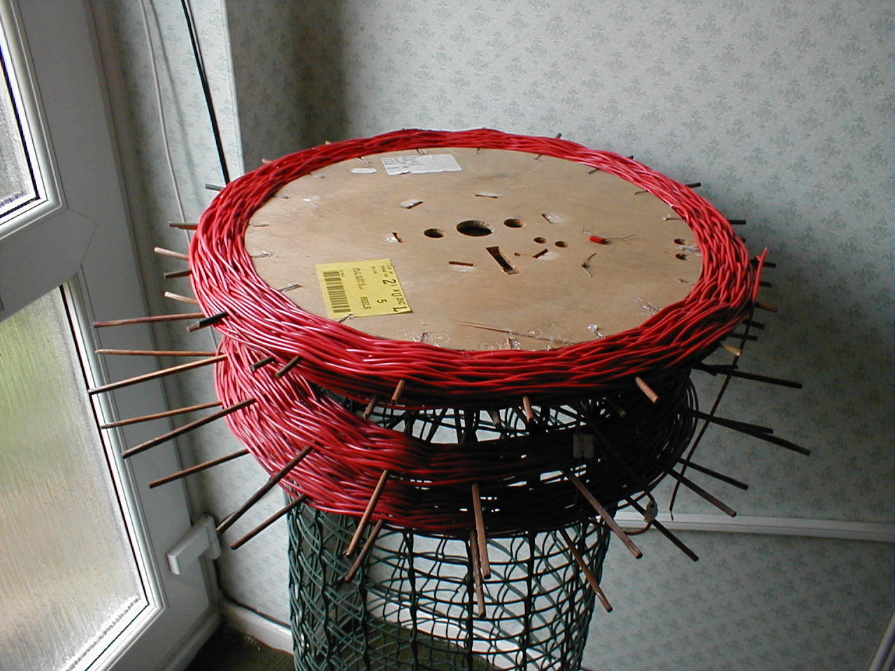
2 extra pies close coupled to original coil gives 9mH with 200m of wire.
So you have resonated your aerial and now find you can not put much current into it. The culprit is the remaining component the resistor. This is made up of the radiation resistance (the useful bit that goes to form the electromagnetic waves) the ground loss, and other losses such as the coil. Unlike the HF (or MF) bands the radiation resistance of a 1/400th wave aerial is tiny, and is usually specifed as milli-ohms. The component which determines the current in the aerial is the ground loss. This will normally be between 25 and 150 ohms. You can do things about this and obviously the lower you can get it the bigger the aerial current you can run and the bigger signal you will radiate. The first thing one tends to do is rush around belting earth stakes in, and then being terribly disappointed that it has not made much difference. There is now a lot of experience accumulated in the LF Group, and a lot of the e-mail messages are archived on Peter Dodds web site
http://web.ukonline.co.uk/g3ldo
The experience of the Group suggests that there is no one way of solving this problem and that each operator must find the best way to optimise the ground resistance in his or her own location. I found that the only way of making progress was to be able to measure the ground losses, and to this end experimented with a simple modified transformer ratio-arm bridge. See the Aerial Loss Measurements page.
The most important part of the 'earth' to connect to is that directly under the vertical rising wire of your aerial. ( added July 2020......I am not quite so sure about this statement now. It may well be true for a plain vertical, but there are doubts when it comes to an inverted 'L'. The doubts are raised after reading the appendix to the LF Experimenter's Handbook. This article by Meissner indicates that he measured the highest ground currents under to rim of the capacity load, i.e.the remote end of an inverted 'L' This might make some sense when you realise that the rf voltage is highest at this point.) If you are going to use multiple earth stakes they should not be closer than about 1.5 times their length, and should be connected back individually to the central stake. Much has been said about running earth 'radial' wires, but remember that a an earth mat with 20 or so 100ft wires which would be very effective on 80m and top-band will be the equivalent on 136kHz, of laying 2m radials on 80m....you probably wouldn't bother. If you do run a radial or counterpoise the best location for it is directly under the top wire if possible. I think the only way to progress is to start with a measurement and try various strategies using the meaurements to decide when to stop and try something else. I found bonding the mains earth in very successful, but I do have 120 feet of armoured cable, buried almost under the top wire. In my sandy soil an 80metre insulated counterpoise wire stapled to the wooden fence and earth at the far end near the remote mast made a significant difference. Incidently this also makes a good standby receiving aerial (!!) collecting as much signal as a 4 foot diameter unamplified 16 turn tuned loop. When you think you cannot make much more progress with counterpoises and earth spikes, you need surprisingly to look up in the air. Yes, by installing more top-load wires you can reduce the earth losses. Extra wires should be spaced at least 70cms from existing top wires to have the effect of giving the aerial more capacity, and should 'cover new ground' to produce a reduction in loss. This effect is fully described in a paper reprinted from 1922, in the Appendix of the LF Experimenter's Handbook. From the point of view of increasing the radiation reistance of the aerial there is not much advantage to be gained by extending the top-wirw much futher than a distance equal to the height of the aerial. What the books do not cover is the decreases in loss gained by increase the top-load capacity. Experiments by Finbar with the spiral design and also with his tower supported Umbrella aerial show that doubling the the top capacity can halve the ground loss (Doubles the square-of-the-aerial-current for the same power, and hence doubles the ERP, even if Rrad stays the same).
The real killers are buildings and trees. Unfortunately you often cannot do much about these items. You can, however, make sure your rising vertical wire is a far as practicable from brick walls and trees or shrubs. Try to avoid going over buildings with the top wire unless you can clear them by a substantial distance (say at least 3m). Keep shrubs and trees well pruned back (tidy) ...the XYL will be impressed...provided you don't overdo it. Moving the vertical drop another metre away from the house can make a lot of difference, particularly after rain. Another place where losses occur is at the insulators. Small white porcelain 'eggs' are of little use at LF because the voltages produced are so high. The insulators need to have a surface path of something like 3 inches. Try to obtain ex marine or commercial ceramic, or pyrex insulators. Dave G3YXM uses toothbrush handles at 500 watts and near the coast a dogs-bone shaped plastic device used, I believe, by crab fishermen is available and recommended. At high power levels it is still possible that you will have losses at the end insulator due to corona discharge, I think this is refered to in the 1938 Admiralty Handbook as 'brushing'. This can be avoided by terminating the wire in a sphere. This may seem a little OTT but it is enough to solder the end of the wire to a small hoop, say 3 or 4 inches in diameter. There is less tendancy for corona discharge from the loop than from the 'sharp' end of the wire. It is the opposite of lightning conductor points. This cause of loss will not show on a low power bridge measurement of course, though you may be able to see and hear it of a quiet dark night. There are some who might say that if you can't, you are not running enough power!! Even then corona discharge is capable of carbonising plastic waste-pipe. Ralph W5GJV has some photos one his 600 metre Group Beacon site.
An excellent and more detailed tutorial on aerials is available on Rik's (ON7YD) site
Edited 1 Aug 2002