
Ground Loss Measurement at LF
Alan Melia G3NYK and Finbar
O’Connor EI0CF
Whilst there are often problems in winding large high inductance coils to resonate LF aerials, the most important factor which needs to be understood and overcome are the losses. Because the electrical size of an normal amateur aerial at 136kHz is much less than a quarter wavelength, a ‘T’ or ‘L’ aerial can be modelled as a capacitor in series with a resistor. The resistive component is made up essentially of two parts, the radiation resistance, and the loss resistance. At frequencies around 136kHz an normal sized amateur aerial will have a loss resistance component of anything up to 100 times the value of the radiation resistance. In this situation, and for a given available RF power level, if we were to halve the loss resistance, we could double the current flowing into the aerial. This would lead to 4 times the radiated signal strength. The majority of the power will still be dissipated in the loss but there will be a 6dB or 1 S point improvement at the receiving station.
I have watched as active stations have grappled with the problems of reducing earth resistance, which is one of the major components of this loss. I did at one time poll the stations on the reflector to find out what form of earth connection they found most efficient. To my surprise there was no ‘golden’ solution, and each seemed to have a particular solution to the problem at his particular location. I became aware that estimating the loss by purely using the aerial current at resonance could lead to some anomalies. Although, after much hard work, most seemed to have used this method effectively, it does require the aerial to be re-resonated with each new configuration and rematched and the PA power level measured and adjusted to be the same as before. Thus the loss in the tuning coil may have changed, the impedance offered to the PA might not be quite the same, and all in all there is room for uncertainties.
I do not have a transmitting capability, but I wished to adjust my aerial so that it would be an efficient signal collector. High values of loss resistance in an aerial will reduce the signal into the receiver as well as reducing the power that is transmitted from it. I had had some contact with Transformer-ratio-arm RF bridges via my professional work and being an avid collector of test equipment had acquired a couple of these units cheaply via Radcom small adverts. My initial experiments on my 136khz wire were made with a Hatfield LE300 bridge. I was able to evaluate the loss when using the mains earth, a single 1.6 metre length of 25mm copper pipe, and an 80metre insulated counterpoise stapled along the bottom arris rail of my garden fence. Finally the effect of connecting all three together. The results were encouraging but more important they were quick and easy to take and repeatable over several days. I have since used the bridge at intervals during a long series of propagation experiments to check that I have not had breakage of any of the top wires, with a consequent change in the output of the aerial.
It occurred to me that it would be very nice if a simple instrument that would give adequate accuracy, could be easily constructed. I have used resistive Wheatstone type RF bridges and noise bridges and found them to sometimes difficult, often with very shallow balance dips. The transformer ratio arm bridges I have used with signal generator source, and a receiver as a detector have always given sharp deep balance dips.


The idea is not by any means original, in fact a simpler unit with transformers is described as an "isolated resistance bridge" in a page on a web site by Johan Bodin SM6LKM dated July 1999 and I believe that the aerial noise-bridge used by Brian CT1DRP uses a similar circuit.(Also see an article by Lloyd Butler VK5BR see references) As it is possible that some may be deterred from trying construction by the difficulties of obtaining the right core material (Lloyd does give some guidance) and winding the transformers, I decided to see whether a standard component would be adequate. I chose a couple of audio hybrid transformers, because I know they were made to very close specification for balance at audio frequencies. One is a standard RS Components item, the other was salvaged from a comms PCB and is wound on a Mullard ferrite pot core. I first connected the secondaries in a centre-tapped configuration, and fed a signal into the primary. I put the centre tap to earth and attached the probes of my dual beam scope to the ‘outsides’ of the secondary. As I expected I got good phase (180 degree shift) and amplitude balance at 10kHz and up to 40kHz. What did surprise me was that this balance was still good at 135kHz (the top frequency of my function generator). Both types of hybrid showed similar performance. I have since found that a standard wide-band pulse transformer from RS with work well, between 10kHz and about 1MHz ( RS Part No.196-375 ) There has been a report of a slight skew in the calibration using this transformer. I have not tested this yet but I believed it could be that the turns ratio was not absolutely correct on the two secondary windings. It may be that when feeding the primary from an unbalanced source there is some residual coupling from ground to one side of the secondaries. This is fairly easy to check using a 1% capacitor and suitable resistor in series, then interchanging the arms of the bridge.
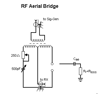
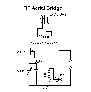
I next ‘lashed up’ a breadboard with flying leads and an antique calibrated variable capacitor, and a potentiometer from the junk box. Unlike a professional laboratory bridge we do not need to cover a wide range of values, so the components in the reference arm are a 250 ohm variable resistor in series with a 500pF variable capacitor. This arrangement means that unlike the professional bridge there is no calculation to perform. Once the components in the reference arm are set exactly equal to the unknown reactance, and because the two arms of the bridge are fed in anti-phase, no current flows in the neutral arm if the bridge and the receiver shows a null. I arranged another optional fixed capacitor that could be strapped in parallel with the variable to cover the expected aerial capacitance of 610 pF. The aerial and ‘radio-ground’ were connected to the ‘unknown’ terminals. The bridge was activated via the primary of the hybrid transformer, and the centre tap was taken to a receiver (SPM-3 ...selective measuring set) At 136 kHz, much to my delight, the balance null was deep and sharp, necessitating several slight alterations of first the capacitor and then the resistor. The capacitor was calibrated from 30 to 350pf, and together with the fixed component gave a value of 603pF. The resistor was then isolated and measured with my digital multimeter, yielding a value of 63ohms. These values are very close to those I measured using the Hatfield LE300 bridge.
I passed on the idea to Finbar EI0CF, who was trying to optimise his aerials at the new house, by the bay side. He built a unit using a bifilar winding on a toroid (TF140-J) and a small oscillator he had built for another bridge and used his SPM-3 as the null detector. He immediately got sensible values, which indicated why he was able to run so much current into his aerial, measuring a loss resistance of 22ohms. He realised that with the simple bridge the receiver ground is connected to the bridge (and aerial ground) so that would make it impossible to measure the aerial grounds without having mains safety earth attached. This is easily overcome by mounting another transformer in the common leg to isolate the receiver. Finbar used this to measure a number of earth configurations as shown in the table below. The bridge starts to give ‘strange’ results as we approach the resonant frequency of the aerial. The aerial should really be modelled as a capacitor, an inductor and a resistor in series. The capacitor and the inductor resonate at the natural resonant frequency of the aerial, usually a quarter-wavelength. It is common to assume that the capacitor cancels out the inductor at resonance, in fact it is the capacitive reactance ( 1/2.pi.f.C ), which cancels with the inductive reactance (2.pi.f.L) The result is a measurement of increasing capacitance (in fact, reducing capacitive reactance) as we approach the resonant frequency. The resonant frequency of the aerial can be found by shorting out the capacitor in the bridge and sweeping the oscillator for a dip. The resistor is adjusted for the deepest dip and the oscillator rocked to find the exact frequency of the resonance. Finbar’s main aerial is resonant up in the 850kHz range.
The bridge can also be used to resonate the aerial at 136. Once a dip has been achieved and the loss resistance found, if the capacitor is shorted out and the loading coil is connected and (only it) is adjusted until a bridge dip is achieved, the aerial should then be resonant. The dip should be deep, and should be deepened by slight adjustment of the resistor (which will then equal the resistance offered to the transmitter). It is possible that if there is not enough adjustment in the loading coil, the bridge may indicate a dip which is not resonance but merely a minimum impedance, with the inductance adjustment and taps available. If the frequency is now ‘rocked’ backwards and forwards no deepening of the dip should be seen if the aerial is actually resonant. If a deeper null is found, this indicates the new resonant frequency of the aerial system and some changes will be needed to the loading coil to achieve resonance back at required frequency in the band.
Finbar has continued to use his version of the bridge to measure an evolving aerial design and has produced results that illuminate a few dark corners of the LF aerial designers art. One of the designs could be well suited to use in a small garden. (but that is another story....well at least another web-page ) Big is certainly easier, but I have copied QRSS from Finbar at 700kms with an estimated ERP of 30mW on this aerial which is only just over 20 feet high and will fit into a 60ft by 60 ft back garden. He has also received S4 reports from 450kms.
Table 1.
Measurements on a 60 foot vertical with four 120 foot capacity
wires
| Earth System |
136 kHz test 1 |
136 kHz test 2 |
500 kHz test 1 |
500 kHz test 2 |
600 kHz |
| 1 | 635 pF | 638 pF | 925 pF | 926 pF | 1235 pF |
| 105 R | 105R2 | 96R | 98R | 105R | |
| 2 | 642 pF | 633 pF | 850pF | 860 pF | 1026 pF |
| 46R | 46R1 | 23R | 24R7 | 25R | |
| 3 | 637 pF | 640 pF | 847pF | 845pF | 1015 pF |
| 38R | 37R7 | 40R | 41R | 50R | |
| 4 | 645 pF | 637 pF | 821 pF | 819 pF | 970 pF |
| 25R | 25R3 | 14R8 | 15R | 11R | |
EARTH SYSTEM
CONFIGURATION AS FOLLOWS :-
1 = Single earth stake (wire about 40 feet (12m) long to the
shack)
2 = Mains earth
3 = outside earth rods and radials (5 earth rods driven into
beach soil + several radials up to over 100m long)
4 = 2 and 3 in parallel
Improved transformer design Added 3rd April 2006 Ref added 12th Sept 2006
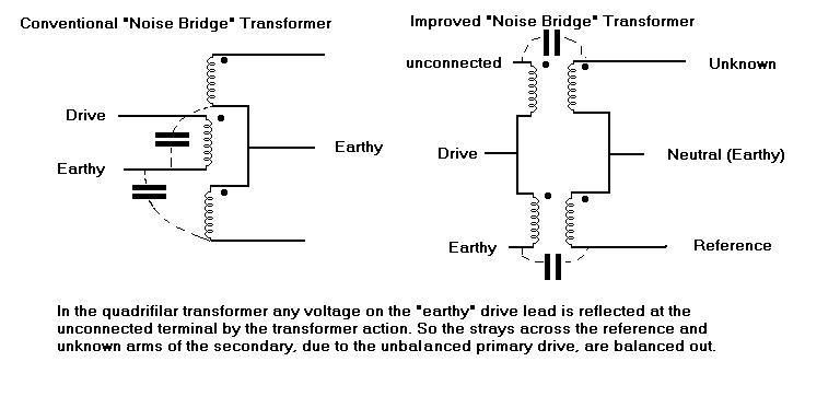
The following idea is basid on an R-X Bridge article in Ham Radio in about 1977 ( "Improvements to the RX Noise Bridge", R.A.Hubbs W6BXI and A.F.Doting W6NKU., Feb 1977 pp 10-20 ). The problem with the usual trifilar wound transformer is that if driven from an unbalaced source the secondary suffers unbalanced strays to ground. This would mean that if you were to swap the components on the arms of the bridge the balance would be different. It is always useful to chack the bridge for this effect with a fixed capacitance and resistance in series in the position of the aerial. Laurence KL1X/GM4DMA has wound a trandformer with 22 turns of 28swg quadifilar on an F 114-77 toroid and achieved a reasonable response betweeb 10kHz and 1.5MHz. As a guide for choosing a different material or manufacturer the inductance of a single isolated winding was 700uH. That will give some loss at the low frequency end, but the phase and ampitude balance is retained.

References
"An LF Antenna Bridge" , Lloyd Butler (VK5BR), Amateur radio (published by the WIA) Oct. 1998, and available through Lloyd's web site http://www4.tpgi.com.au/users/ldbutler/LFBridge.htm
(c) G3NYK 2006