Experiments with a Top-loaded Vertical Aerial
Alan Melia G3NYK and Finbar O’Connor EI0CF
Finbar did some experimenting very early with a novel form of Top-loaded aerial for LF. This was stimulated by a short piece in Pat Hawker’s Technical Topics column in the RSGB Radcom in November 1974 [3], and revisited in May 1988. The original write-up carried the source references to an IEEE Transactions paper [1]on LF and VLF, and a Canadian Broadcasting Corporation Engineering Review [2] with some practical details of an MF BC aerial tests. The construction seemed quite simple, and Finbar experimented for a while before the UK gained access to 136Khz. After our sucessful measurements with the simple ground loss bridge, Finbar was keen to see if the aerial could be developed into a form suitable for small gardens as a way of encouraging some more activity. The only countries with licences were to the East of Finbar and the few with permits in Canada were a L O N G way away.
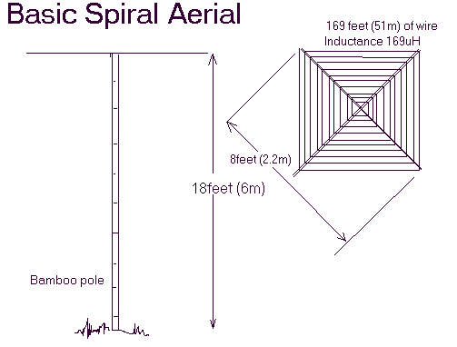
The configuaration described by Pat in the column was a top-loaded vertical with the loading inductance in the form of a spiral. Finbar constructed this using an 18foot bamboo pole (probably the type that used to form the centre of rolls of carpet) with a horizontal cross made out of a pair of horticultural bamboos canes about 8 feet long. The coil was simply secured to the cross-arms with (plastic ratchet) cable ties. He determined to measure the aerial at each stage of the evolution, and the results have proved to be an invaluable insight into aerial system (or ground) losses. The initial measured results were interesting and the aerial was developed by adding capacity loading above the spiral and increasing the inductance of the spiral. The idea was that an aerial in a small garden will probably only have a small capacity, and so will need a large coil to bring it to resonance. A large coil is difficult to build and has some considerable loss unless engineered on a grand scale. Also there was a suggestion that inductive top loading decreased the effect of environmental losses, those due to nearby trees and building......difficult to avoid in a small garden.

Initially all the measurements done on the aerial were using the bridge described the the Gound Loss Measurement article. It was intended eventually to measure some field strengths, but the early winter gales destroyed the structure before we could accomplish that part of the experiment. Nevertheless Finbar did load up the last structure with about 100 watts and made some qsos into UK and was copied by me at a distance of about 700kms. We regarded this somewhat of a success for an aerial no higher than about 22 feet to the top of the capacity load and capable of being erected in a 60 foot square garden.
The stages of evolution were
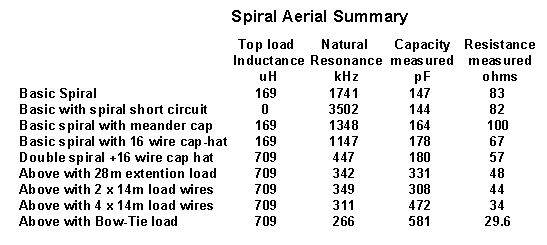
1. A single spiral at 18 feet height, with a 30 foot ‘downlead to the operating position Inductance of spiral = 169uH
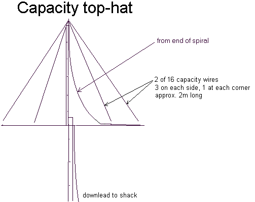
2. The above with some meander capacity wire added above the spiral cross-arms.
click here for a photographs of Finbar's aerials

3. A ‘double’ spiral .... after winding a spiral inductor to the limit of the cross-arms clipped to the lower side of the cross-arms, the spiral was continued in the same winding sense on top of the cross back towards the centre pole. This makes quite a sustantial inductor (inductance = 705 uH ) as can be seen by the figures for the natural resonance of the unloaded aerial.
4. An 80 foot ( 28m
) wire was attached to the peak of the aerial and run away
horizontal as a capacity loading wire.
(Model A )
5. The 80 foot top-load was reconfigured to be 40 feet ( 14m ) each side of the supporting pole. (easier in a small garden.) (Model B )

6. Two further 40 foot top-load wires were run, not at right angles due to the shape of Finbar’s plot. (Model C )
7. The two ends of the two pairs of top wires were joined to form a ‘bow-tie’ configuration. ( Model D )
The details of the layout and inductance of the spiral is given in the measurement tables
The results were very consistent until we reached the last stage when it seemed that things started to go awry. It occured to us that the spell of dry weather that Malin had been enjoying had just come to an end and Finbar had done the last measurements in drizzle. This ‘fortunate’ occurance also helps us to understand some of the effects of weather on an aerial system, and we were able to complete several sets of comparative meaurements on Model D under different weather conditions.
The results of the RF bridge measurements have been assembled on separate pages. Click here for measurement tables.
These measurements were concluded at the end of 2001. Unfortunately before we were able to carry out field strength measurements on the configuations, the construction was destroyed beyond repair. The aerial has proved that it does work, as the last configuration, Model D the double spiral with the bowtie top-load, was excited with 100watts of RF and worked several stations in the UK being copied easily by me at about 700kms range in daytime. The first bad December gale wrecked the bamboo construction beyond repair. Finbar's location at Malin on the shore of Trebreager bay is wide open to the Atlantic winds.

Is there to be an advantage to be gained by this aerial ? To
my mind the greatest advantage is that, in a limited area of
'real estate', we were able to construct a relatively small
aerial which only required a loading coil of about 2mH to
resonate at 137kHz. This size of coil is a considerably easier
thing to construct that the 5-6mH coil that would be required by
a strapped 80m dipole or a 126 foot end fed wire. Also because it
would require less wire the coil losses would be considerably
reduced. The series of experiments has also demonstrated the
effect, flagged up by Laurie G3AQC. When there is no more to be
gained in reduced ground loss, by running radials or ground
spikes, then increasing the capacitive top-loading to cover fresh
ground can be very productive. The figures on the graph are taken
at 122kHz, to stay as far as possible away from the natural
resonance of the aerials.
This effect can be seen on all types of vertical, inverted 'L' and 'T' aerials. All of the above measurementson the spiral used Finbar's normal ground system, which was described at the end of the page on the Aerial Loss Bridge. Some extra earth stakes and 'radial wires' were run out for the tower ( a 17m crank-up supporting a near vertical wire with different numbers of top-load 'umbrella' wires ) measurements plotted above. Several of these terminated in a stake in the seashore. The extra stakes do not seem to have made as much difference as doubling the top-load capacity. A good explanation of the technical background is given in a 1922 paper in the Appendix to the LF Experimenter's Handbook (RSGB). The graph above shows that if you double the top-load capacity you halve the loss resistance. All aerials will not lie on the same line, because there is an element in the equation for ground skin depth or penetration, which will vary at different sites with different ground properties. The slope of the line at your site should be about the same. Thus if you have 100ohms loss resistance with 300pF you could reduce it to 50 ohms by increasing the capacity to 600pF. It does support the old adage of "filling the sky with wire" !!
The above experiments have also proved the utility of the ground-loss bridge and that there is really no subsitute for a systematic series of carefully made measurements. As a by-product of these tests we have also learned some information about the effects of weather on the aerials. That subject will be described on a separate page.
It is possible that this form of constuction could be used to make a very effective resonant top-band (160m) vertical aerial. A further suggestion would be that if an insulated mast were available, an advantage could be gained by forming the 'down-lead' from the spiral into a helix round the support mast. This technique was used in the CBC paper [2] for one aerial. This form of 'continuously loaded vertical' is used to good effect by Toni HB9ASB.
Click here for 2 photographs of the experimental spiral-topload aerials
References
1. H.Bhojwani and L.W.Zelby, "Spiral top-loaded
antenna : characteristics and design", IEEE Transactions on
Antennas & Propagation, May 1973, pp 293-298
2. J.L.Marshal, "Experiments with Two Novel Compact Antennas for Medium Wave Broadcasting" Canadian Broadcasting Corporation Engineering Review, Vol. 12, June 1974
3. Pat Hawker, "Technical Topics", Radio Communication (RSGB), Novenber 1974