A Problem with the Datong VLF Converter on 73kHz
As a result of a query from Roger G2AJV, we have discovered a potential problem on the Datong VLF Converter. This unit converts frequencies below 500kHz up to the 28MHz band. Roger found he had a high level spurious signal in the 73kHz band on two samples of the unit. Other units may have this spurious but it may well fall outside the band. This problem could occur with any LF converter using 28MHz as the IF. It will not be problem with converters using 10MHz or 4MHz as these units will use a fundamental mode crystal oscillator.
The problem turns out to be a function of the crystal local oscillator circuit. This is a third overtone crystal oscillator running at 28MHz. Most overtone oscillator circuits above 20MHz, are designed to drive the crystal at almost 3 times its fundamental frequency. The third overtone frequency is usually about 60 to 70 kHz lower than three times the fundamental frequency, due I believe to 'internal friction' in the quartz. The overtone oscillator circuit must be designed to be degenerative (not have gain) at the crystal fundamental frequency. In the Datong case there is a substantial amount of fundamental frequency in the oscillator output. The third harmonic of the fundamental energy beats with the third overtone energy giving a strong signal in the 70kHz region.
No response has been received from David Tonge, and I believe he has ceased manufacturing these units. I believe that the problem my be caused by a more active crystals than was used when the converter was first designed. I think the solution may be to reduce the amount of feedback in the oscillator circuit so that the crystal is not driven so hard. I do not have a circuit diagram for the unit so I can only make suggestions for trials. It will be necessary to monitor the local oscillator output, probably at the IF port. Look for the fundamental frequency on a receiver with an S-meter (it will be about 20-30kHz above 1/3rd the overtone frequency). If the oscillator is working properly no signal should be found. If there is a detectable signal, (check by switching the converter on and off) then it may be possible to reduce the feedback in the oscillator, until the fundamental signal disappears completely.
Most of the amateur radio handbooks I have scanned seem to skate over the topic of reliable overtone operation, some even have a sloppy inter-change of the terms overtone and harmonic.
There is an a rf choke in the emitter of a Clapp style oscillator. The value of this component should be selected such that the circuit does not have gain at the crystal fundamental frequency. This is usually achieved by ensuring that the resonant frequency of the parallel circuit of this choke and the lower capacitor is the geometric mean of the fundamental and third overtone frequencies (1). Increasing the value of the lower capacitor will reduce the feedback, but then the choke value will need to be reduced. Thus there may be a little 'cut-and-try' required
Reference
1. "A Modern, Professional Look at the Design of Stable, Crystal Oscillators Working at High Frequencies". Bernd Neubig, DK1AG, VHF Communications 1/91 p38
(Part 2 in 2/91)
Addenda
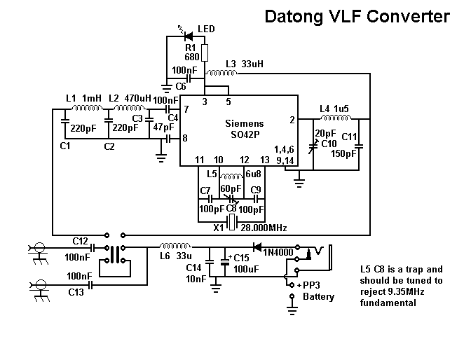
Since this was written a circuit diagram for the converter has be obtained. The unit uses an SO42 mixer and uses the two tail transistors as a rather 'brute force' oscillator. The trimmer capacitor in series with the coil and crystal is intended in the original data sheet to suppress drive to the crystal at the fundamental ( about 9.36MHz) frequency. Although the data sheet for the converter suggests that it can be adjusted to set the converter on frequency, this is NOT how it should be set. Listen on the receiver on the output of the converter to the a frequency about 60 to 80kHz above the (crystal frequency)/3, and adjust the trimmer capacitor so there is no signal at this frequency. Switch the converter on and off with the push-switch to check. If the crystal is being driven at the fundamental there will be a very strong signal in the receiver. As a result of this requirement, it is NOT POSSIBLE to trim the converter to give easy frequency accuracy on the output receiver, so you will have to remember the offset.
Having made there comments the converter does work quite well, but it is intended to be used for BC stations and used on a short length of wire. It has a lot of gain, so if fed from a long wire it will produce a lot of intermodulation products in the 136kHz band. If it is used with a passive loop it works extemely well and has been used for several years by Mike G3XDV and Peter G3LDO. Mike suggests that to use it with a long wire the wire should be fed to the conveter via a 1k0 potentiometer, which acts as an attenuator. A simple low-pass filter would probably also help to keep out the strong BC stations.