
TX Module Combiners
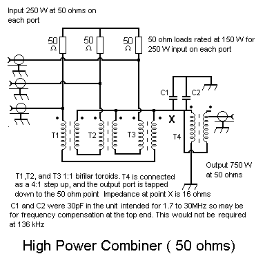
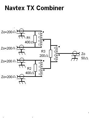
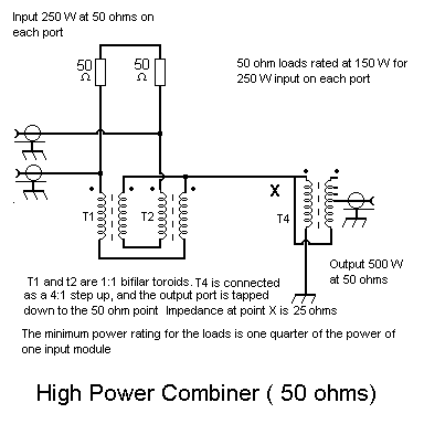
The transmitter module combiner circuits shown below were copied from commercial circuits. The "Navtex" combiner was in a 1kW transmitter at 518kHz, but is only really useful for 2, 4, or 8 modules, whereas the other design can be expanded to any number of modules (notice the 'circular' connection of the hybrids). Note that without the output step-up transformer the output impedance is 1/N times the input impedance.
A rule-of-thumb I use for calculating the winding turns for wideband transformers is that the unloaded winding reactance at the lowest frequency of operation should be 3 times the feed impedance. It is possible that for a narrow-band design like 136kHz this could rise to 5 times, as we are not really interested in a decade bandwidth. For example the reactance of a 50ohm fed winding should be at least 150 ohms which is 177uH at 135kHz. The windings should be on high permiability ferrite torroid cores in a bifilar fashion. The other factor is the power handling capacity. If there is too little ferrite it will get noticably hot. My motto is use the biggest core you can get. If this still gets hot, increase the cross-sectional area by putting the windings on two stacked cores as Dave G0MRF has done.


