Notes for use of active devices in the
ACN Network Analysis program
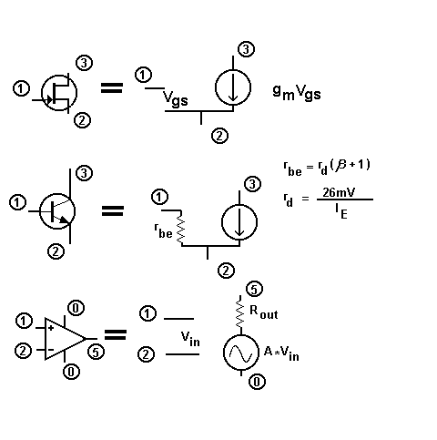
The method used to model active devices is similar to that used in the program for passive devices. A FET is simply modelled as transconductance (Vgs*gm). If you require to consider inter-electrode capacitances for instance these should be added as additional external passive components. Bipolar transistors and op-amps are dealt with similarly. The diagram below gives a pictorial representation of how a FET , a BJT, and an Op-amp are modelled and how the parameters are calculated for the net list.

The main parameters you will want for a bipolar transistor are the gain (beta) and the operating current. This allows the base current to be calculated and the output signal from the transistor to be determines as beta * Ib. The one characteristic that is not modelled is the reduction in gain at higher frequencies. This can be modelled as a external resistor in the collector, rc and a capacitor between collector and emitter Cob . This gives the appropriate roll-off of 6dB per octave.
To model the FET you will only need to have a figure for the transconductance, gm.
For the Op-amp you will need a vlue for the open-loop gain ( in V / V ), and the output impedance rout. Again frequency response can be modelled with an external capacitor, giving a 6dB per octave slope, with the output impedance.
The program has proved to be very useful, though there may need to be some intelligent external modelling to get correct opertaion at frequencies approaching the unity gain, transition frequency.