Aerial Measurements with Selective Level Measuring Sets
Using the Wandel and Goltermann SPM-12, the PS-12, and the RFZ-12
The RFZ-12 is an accessory for the SPM-12 and PS-12 combo. The SPM-12 is a selective measuring set with a range from 200Hz to 6MHz , measuring levels down to -120dBm. The PS-12 is a matching source which can be locked to the synchronised local oscillator in the SPM-12, and provides an output of up to 0dBm into 75ohms. I was lucky enough to acquire an RFZ-12 with my units as well. This is titled as a "Reflexion Measuring Attachment", and is in effect a return loss bridge covering 200Hz to 6MHz. It has switched accurate loads inside for all the common line impedances but it also has the facility to attach an external load via the standard 3 in-line 4mm connectors. The attachment is driven from the PS-12 and the meter in the SPM-12 is used to measure the return loss directly in dBm.
I have used the attachment in a different mode to measure the characteristics of an LF aerial. If a variable capacitor and a 250ohm variable resistor, connected in series, are connected to the external load sockets, the attachment becomes an aerial bridge. The aerial is connected to the "TEST OBJECT" port and the variable capacitor and variable resistor are adjusted to achieve best null on the SPM-12 in the traditional way of bridge balancing. Once balanced is achieved the values of the resistor and capacitor can be measured on a hand-held digital component tester (LCR meter)
In tests on my aerial I was able to measure similar values to those recorded on a laboratory RF bridge. The only problem was that, as I expected, at night the 0dBm level from the PS-12 is insufficient to allow an accurate dip. The dip depth was -90dB but due to the signals being received on the test frequency the needle was bouncing around and it was difficult to ascertain the effect of the changes on the reference components. I suspect another 20 to 30 dB of gain might be required after the PS-12 output to achieve a null that is not corrupted by received signals. When using the SPM-3 SLMS with an external source we found we needed about 2 to 5 volts rms to achieve an accurate null, with sufficient discrimination to measure to about 0.5ohms and 5pF. It is probably preferable to do aerial measurements in the daytime when interfering signal strengths are at least stable, and there are generally less TVs sweeping across the band.. One of the major problems when using a Selective Level Measuring set with radio signal from an aerial is that their Intermodulation performance is not up to that of a good radio receiver. Part of this is due to the lack of any selectivity inthe front end of the system. I suspect if you are going to use this sytem it may be necessary to employ at least a low pass filter at the input to reject the the BC stations.
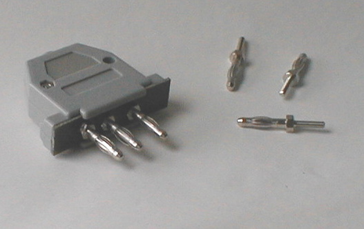
Construction of 3-pin plugs for W&G equipment
The following pictures show some ideas for the construction of 3-pin plugs to fit W&G selective level measuring sets such as the SPM-3 and SPM-12. The cenrtre spacing of the pins is 9mm and 12mm, so that the plug is non-reversible. The shells are from standard 25pin D connectors. There is enough roon in the connector to mount a 3.5mm jack for a pair of head-phones for the demodulator on the SPM-12 or to mount a BNC socket in case of an adaptor for the SPM-3. The base is a piece of standard thickness PCB material. Because this is a little thicker that D-type pucgs it will be necessary to file the shells slightly on the fixing screw lugs.
All the parts were obtained from Rapid Electronic Ltd catalogue www.rapidelectronics.co.uk . The pins are Part No 17-0690 including fixing nuts and the D-series shells are Part No.15-0240